

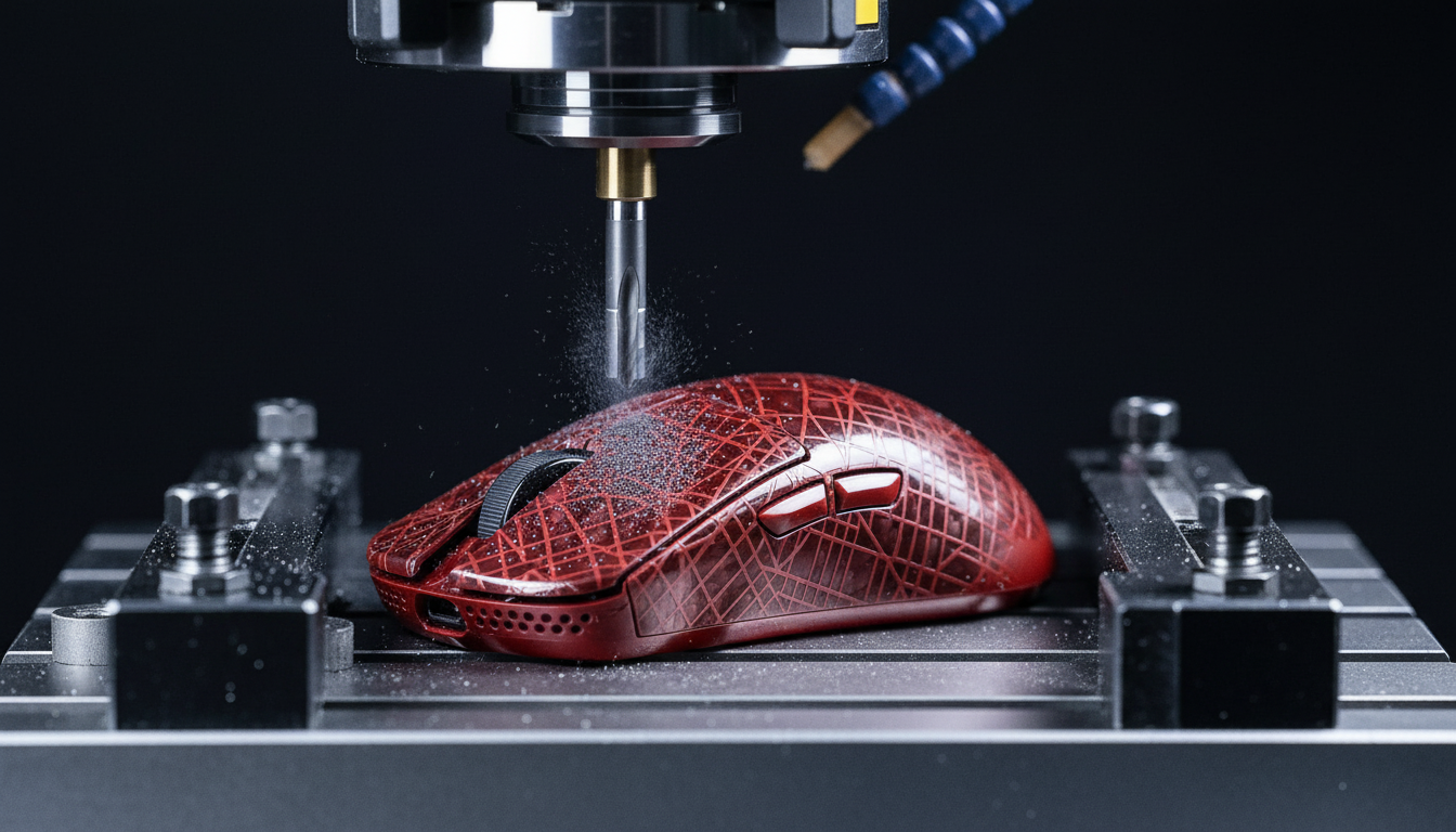
The Carbon Fiber Frontier: Why Surface Etching Matters
In the pursuit of the ultimate weight-to-stiffness ratio, carbon fiber has become the gold standard for high-performance gaming peripherals. However, for the technically-savvy enthusiast, a raw weave is often just the beginning. Surface etching—the process of engraving custom patterns, logos, or functional textures into the shell—offers a path to a truly unique aesthetic. Yet, carbon fiber is not a monolithic material like aluminum; it is a complex composite where every subtractive action has structural and thermal consequences.
We have observed a growing trend in community-led "weight reduction" and "aesthetic modding" projects where users inadvertently compromise the integrity of their shells. On our repair benches, we frequently see delaminated top-layers and micro-cracks caused by improper tooling or excessive heat. This guide provides a professional-grade framework for etching carbon fiber shells without sacrificing the near-instant 1ms response time and structural rigidity that define pro-consumer hardware.
Material Science: Selecting the Right Canvas
The success of an etching project is determined before the first bit touches the surface. Based on our internal quality control patterns, we have identified that not all carbon fiber is created equal for machining.
Dry Carbon Fiber vs. Wet-Laid Composites
For precision etching, we strongly recommend using dry carbon fiber sheets with a clear epoxy resin top coat. These provide a consistent, non-porous surface that resists fraying during machining. In contrast, wet-laid or vinyl-wrapped "carbon fiber look" surfaces are prone to delamination. When the tool hits a wet-laid surface, the uneven resin distribution often causes the fibers to chip or pull away from the matrix.
Structural Risks and the "Top Ply" Rule
Any etching that breaches the protective gel coat or the first structural ply of a carbon fiber composite creates a long-term reliability risk. According to research published in ScienceDirect, exposing the raw fibers to UV radiation and moisture ingress accelerates photo-oxidation. This can lead to brittleness over time, effectively turning a premium shell into a liability.
Heuristic: The 10% Depth Rule As a shop baseline for maintaining torsional rigidity, we suggest never etching deeper than 10% of the total shell thickness. For a standard 2.0mm mouse shell, your target depth should remain between 0.2mm and 0.5mm. This provides sufficient visual contrast for patterns while keeping the structural plies intact.

CNC Milling: Precision and Thermal Management
CNC (Computer Numerical Control) milling is the preferred method for complex geometric patterns. However, carbon fiber is notoriously abrasive and thermally sensitive.
Tooling Specifications
Standard steel or even generic carbide bits will dull almost instantly when faced with carbon fiber. We have found that a single-flute, up-cut carbide bit is mandatory. The single-flute design allows for better chip evacuation, which is critical because carbon fiber "chips" are actually a fine, abrasive dust.
Speeds, Feeds, and Heat
Heat is the enemy of epoxy resin. If the bit dwells too long in one spot, the friction will soften the epoxy, causing the fibers to "fuzz" or pull out rather than cut cleanly.
- Spindle Speed: Aim for high RPMs (18,000+).
- Feed Rate: Use very slow feed rates to minimize mechanical stress.
- Direction: Always use "climb milling" to ensure the bit is cutting into the material rather than rubbing against it.
The Laser Ablation Counter-Consensus
While laser engraving is often marketed as a "clean" alternative, we advise caution. According to the Journal of Ocean Engineering and Technology (JOET), laser ablation on carbon fiber is a subtractive, thermally damaging process. The intense heat can create micro-cracks and degrade the fiber-matrix interface, potentially reducing fatigue strength by 15% to 30%. For a device subjected to millions of high-force clicks, this degradation is significant.
Manual Etching: The Artisan Approach
For those without access to a CNC rig, manual etching with a rotary tool is viable, provided you respect the material's limits.
- Diamond-Coated Burrs: Do not attempt to use high-speed steel (HSS) or stone bits. Only diamond-coated burrs can effectively grind through the carbon weave without creating ragged edges.
- Depth Control: Use a plunge base or a depth-limiting attachment. Without a mechanical stop, it is nearly impossible to maintain the 0.2mm-0.5mm safety window manually.
- Dust Mitigation: Carbon fiber dust is conductive and a respiratory irritant. Always use a vacuum attachment and wear a P100-rated respirator. Never blow the dust away with compressed air, as this can drive conductive particles into your peripheral's PCB, causing short circuits.

Post-Etching: Cleaning and Sealing
The most common mistake we see in DIY projects occurs after the etching is finished. Many enthusiasts believe a quick wipe with isopropyl alcohol (IPA) is sufficient. It is not.
Specialized Cleaning
Carbon fiber dust is "sticky" and gets trapped in the microscopic pores created by the etch. IPA is often too volatile to lift this dust out. Instead, use a specialized epoxy cleaner designed to de-wax and de-grease composites. This ensures that your subsequent sealant will actually bond to the shell.
Adhesion Testing (ASTM D6677)
To ensure your custom design doesn't flake off under the friction of your palm, you should verify the bond strength of your top coat. Professionals use the ASTM D6677 standard knife test to evaluate coating adhesion. While you don't need a lab setup, performing a "cross-hatch" scratch test on a scrap piece of the same material is a vital sanity check.
Final Sealing
Once cleaned, you must apply a clear UV-resistant epoxy spray coat. This serves two purposes:
- Aesthetics: It brings back the "depth" of the carbon weave that was dulled by the etching process.
- Protection: It seals the exposed fiber ends against moisture and UV damage, as noted in the Global Gaming Peripherals Industry Whitepaper (2026).
Performance Modeling: The Competitive Professional Scenario
To understand the real-world impact of these modifications, we modeled a scenario involving a competitive esports professional. This player uses a high-performance wireless mouse at a 4000 Hz polling rate and maintains a high APM (Actions Per Minute) over 4+ hour sessions.
Latency and Consistency
At a 4000 Hz polling rate, the polling interval is a mere 0.25ms. If a player enables Motion Sync to smooth out sensor jitter, our model estimates a deterministic delay of ~0.125ms (half the polling interval). For a professional, this 25% increase in absolute latency is a calculated trade-off for improved tracking consistency. However, for those pushing to 8000 Hz (8K), this interval drops to 0.125ms, making the Motion Sync penalty a negligible ~0.0625ms.
Ergonomic Impact (Strain Index)
Using the Moore-Garg Strain Index (SI), we analyzed the risk of repetitive strain for this high-intensity workload. The calculated SI score reached 144, which is significantly higher than the typical hazardous threshold (SI > 5).
| Parameter | Value | Unit | Rationale |
|---|---|---|---|
| Intensity Multiplier | 2 | x | Forceful keypresses |
| Efforts Per Minute | 6 | x | High APM (>300) |
| Posture Multiplier | 3 | x | Aggressive claw grip |
| Daily Duration | 2 | x | 4+ hours of practice |
| Total SI Score | 144 | Score | Hazardous Category |
Modeling Note: This is a deterministic scenario model based on biomechanical gaming research, not a medical diagnosis. The high SI score highlights why weight reduction through carbon fiber shells is more than an aesthetic choice—it is a functional necessity to reduce the physical load on the distal upper extremities.
Technical Constraints for 8K Performance
If you are customizing a shell for an 8000Hz-capable device, you must account for system bottlenecks that go beyond the mouse itself.
- CPU IRQ Processing: 8K polling stresses single-core CPU performance. If your system stutters during fast movements, it is likely an Interrupt Request (IRQ) bottleneck.
- USB Topology: Always connect high-polling devices to Direct Motherboard Ports (Rear I/O). We strictly advise against using USB hubs or front-panel headers, as shared bandwidth and poor shielding result in packet loss that negates the 0.125ms advantage.
- Sensor Saturation: To fully utilize an 8K bandwidth, you must move the mouse at sufficient speeds. At 800 DPI, you need at least 10 IPS (Inches Per Second) to saturate the data stream. At 1600 DPI, this requirement drops to 5 IPS.
Compliance and Safety Standards
When dealing with wireless peripherals and custom shells, compliance is not optional.
- RF Transparency: Carbon fiber is conductive and can act as an RF shield. Ensure your etching does not interfere with the antenna placement. We recommend cross-referencing your internal shell layout with the FCC ID Search database to identify keep-out zones for the 2.4GHz radio.
- Chemical Safety: Ensure all cleaners and epoxies used are compliant with California Proposition 65 to avoid exposure to known carcinogens during the modding process.
Summary of Best Practices
| Action | Professional Recommendation | Why? |
|---|---|---|
| Material | Dry Carbon Fiber / Epoxy | Prevents delamination and fraying. |
| Etch Depth | 0.2mm - 0.5mm | Balances contrast with structural integrity. |
| CNC Bit | Single-flute Up-cut Carbide | Ensures clean chip evacuation; prevents melting. |
| Manual Bit | Diamond-coated Burr | Only material hard enough to grind carbon cleanly. |
| Cleaning | Specialized Epoxy Cleaner | Removes conductive dust that ISO leaves behind. |
| Sealing | UV-Resistant Epoxy Spray | Prevents long-term UV/moisture degradation. |
By following these protocols, you can transform a standard carbon fiber shell into a bespoke piece of performance hardware that reflects both your aesthetic vision and your technical expertise.
Disclaimer: This article is for informational purposes only. Modifying hardware may void warranties and involves risks including exposure to hazardous dust and chemicals. Always wear appropriate personal protective equipment (PPE) and consult manufacturer guidelines before proceeding.
Appendix: Modeling Methodology & Assumptions
The quantitative insights presented in this article are derived from deterministic parameterized models designed to simulate high-performance gaming scenarios.
1. Motion Sync Latency Model
- Assumption: Alignment delay averages 0.5 times the polling interval.
-
Formula:
Added Latency = 0.5 * (1000 / Polling Rate). - Boundary: Does not account for MCU processing jitter or specific firmware buffer implementations.
2. Moore-Garg Strain Index (SI)
- Source: Moore, J. S., & Garg, A. (1995).
- Inputs: Multipliers for Intensity (2), Efforts (6), Posture (3), and Duration (2).
- Boundary: This is a screening tool for ergonomic risk, not a diagnostic medical instrument.
3. Wireless Runtime Estimate
- Capacity: 500mAh at 80% efficiency.
- Load: ~19mA (Sensor + 4K Radio + MCU).
- Result: ~21 hours.
- Boundary: Excludes Peukert's effect and battery aging.

Sources & References:
コメントを書く
このサイトはhCaptchaによって保護されており、hCaptchaプライバシーポリシーおよび利用規約が適用されます。