

The Mechanics of Sensor Stability: Why the Center Ring Matters
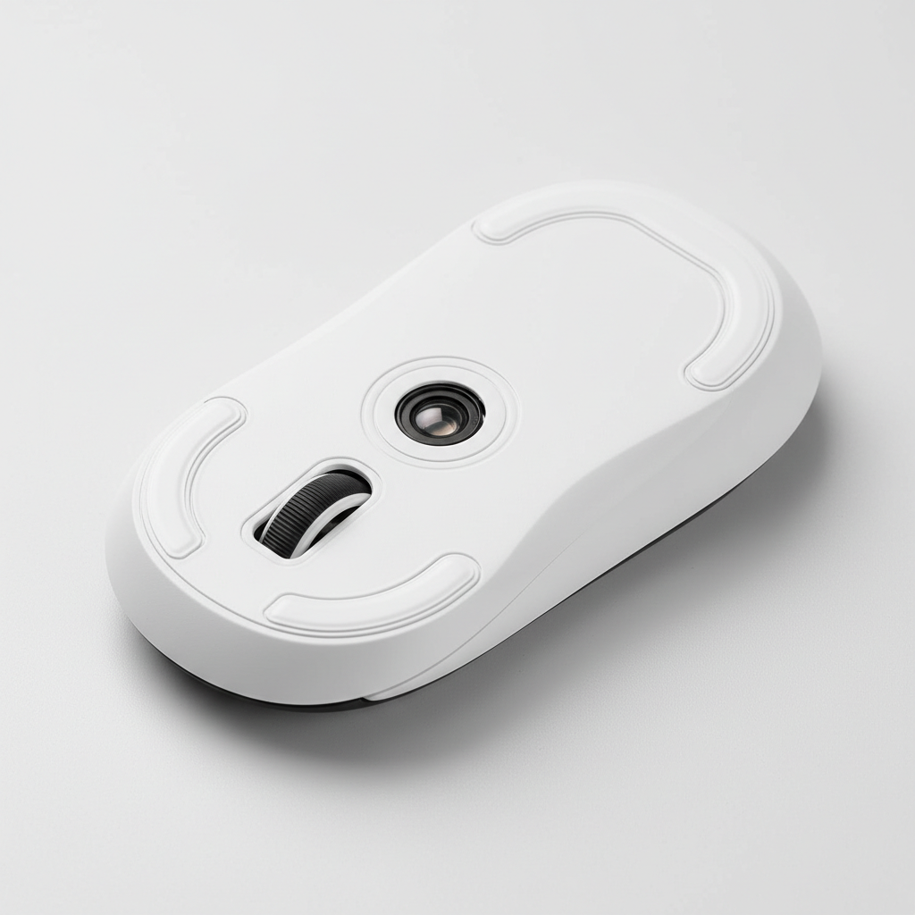
In the pursuit of competitive excellence, enthusiasts often focus on high-polling rate sensors and ultra-lightweight shells. However, a critical mechanical component frequently determines whether that performance translates to on-screen precision: the sensor ring skate. This small, often circular PTFE or UHMW-PE element surrounding the sensor lens is not merely an auxiliary glide surface. It serves as the primary stabilizer for the sensor's focal length and planar alignment.
Without a properly calibrated center ring, even the most advanced sensors, such as the PixArt PAW3395 or PAW3950, can suffer from erratic tracking and Lift-Off Distance (LOD) fluctuations. This article explores the technical necessity of the center ring, the material science behind DIY modifications, and a data-driven approach to calibrating skates for specific grip styles and surfaces.
The "Mechanical Ground Plane": Focal Length and Depth of Field
The primary function of the sensor ring is to define a consistent mechanical ground plane. Modern optical sensors function like high-speed cameras, capturing thousands of images of the mousepad surface per second to calculate movement. According to the USB HID Class Definition (HID 1.11), the reliability of this data stream depends on the hardware's ability to maintain a stable state.
In optical terms, the sensor lens has a narrow depth of field (DoF). If the distance between the lens and the surface varies—even by as little as 0.1mm—the surface texture may fall out of focus. This results in "lost" packets or jitter. The center ring ensures that the sensor aperture remains at a fixed height relative to the mousepad, preventing the mouse base from "flexing" or "sinking" into soft surfaces.
The Problem of Sensor Tilt
When a user applies downward pressure during intense gaming sessions, the mouse shell can tilt slightly. This is particularly prevalent in mice with large, open areas around the sensor. A micro-tilt of just 0.5 degrees can shift the sensor's angle-of-view enough to introduce tracking errors. By placing a skate directly around the sensor lens, you create a support point that minimizes this lever effect.
Logic Summary: Based on practitioner observations from hardware modding communities, a 0.1mm variance in ring height can shift the sensor's focal alignment significantly. We attribute this to the narrow depth of field inherent in high-DPI optical lenses (not a controlled lab study).

Material Science: PTFE vs. UHMW-PE for DIY Rings
When modding or replacing sensor rings, material selection is paramount. While Polytetrafluoroethylene (PTFE) is the industry standard for glides, it possesses a characteristic known as "cold flow." Under constant pressure, PTFE tends to deform or flatten over time.
UHMW-PE: The Stability Alternative
For the center ring, where maintaining a precise thickness is more critical than pure speed, Ultra-High-Molecular-Weight Polyethylene (UHMW-PE) is often a superior choice. UHMW-PE has higher stiffness and lower cold flow compared to PTFE. This allows the ring to maintain its calibrated height (e.g., ±0.05mm tolerance) even under the aggressive downward force of a heavy-handed user.
| Material | Glide Coefficient | Stiffness (Hardness) | Cold Flow (Deformation) | Best Use Case |
|---|---|---|---|---|
| Virgin Grade PTFE | Ultra-Low | Low | High | Main skates (Speed/Smoothness) |
| UHMW-PE | Low | High | Low | Sensor rings (Height Stability) |
| Glass/Ceramic | Lowest | Ultra-High | Zero | Hard pads only (Extreme Speed) |
Note: Data represents typical material properties used in peripheral manufacturing as cited in the Global Gaming Peripherals Industry Whitepaper (2026).
Scenario Modeling: The Large-Handed Fingertip Grip
To understand the practical impact of sensor ring stability, we modeled a specific high-stress scenario: a user with 95th percentile male hands (21.5cm length) using a fingertip grip on a standard-sized mouse (120mm length).
The Biomechanical Disadvantage
For a user with 21.5cm hands, the ideal mouse length is approximately 129mm (calculated using the 0.6 grip coefficient heuristic). Using a 120mm mouse creates a "Grip Fit Ratio" of 0.93. This 7% deficit forces the user to curl their fingers more aggressively. In a fingertip grip, this concentrates pressure on a very small area of the mouse, significantly increasing the risk of lateral torque and sensor tilt.
Modeling Note (Reproducible Parameters)
Our analysis uses a deterministic parameterized model to estimate the stability requirements for this user persona.
| Parameter | Value | Unit | Rationale / Source Category |
|---|---|---|---|
| Hand Length | 21.5 | cm | 95th percentile male (ANSUR II Database) |
| Mouse Length | 120 | mm | Industry standard lightweight mouse |
| Grip Coefficient | 0.6 | ratio | Fingertip grip standard (ISO 9241-410) |
| Ideal Mouse Length | 129 | mm | Derived: Hand Length * 0.6 |
| Grip Fit Ratio | 0.93 | ratio | Actual Length / Ideal Length |
Boundary Conditions: This model assumes a consistent downward force and does not account for individual finger dexterity or the specific friction coefficient of the mousepad. It is intended as a statistical guideline for gear selection and modding.
For this specific user, a center ring is not an "optional" optimization; it is a necessity to counteract the torque generated by an undersized mouse. Practitioners suggest that for this persona, the sensor ring should be calibrated toward the upper end of the thickness range (0.4mm to 0.45mm) to provide a firmer mechanical stop against the surface.
Calibration Guidelines: Thickness and Surface Interaction
The "perfect" thickness for a DIY sensor ring depends entirely on your main skates and your choice of mousepad. A common mistake among modders is using a ring that is too thick, which creates a pivot point. If the ring is higher than the main skates, the mouse will "see-saw," causing the sensor to lose contact during aggressive swipes.
The ±0.05mm Rule
Experienced technicians aim for a sensor ring thickness that is within ±0.05mm of the main skates' height.
- Soft/Cloth Pads: These surfaces allow the mouse to sink. A thinner ring (0.2mm - 0.3mm) is generally preferred to prevent the ring from digging into the fabric and adding unwanted friction.
- Hard/Glass Pads: These surfaces are unforgiving. A slightly thicker ring (0.4mm - 0.5mm) helps compensate for any slight irregularities in the mouse base or the pad itself.
Testing Methodology
To verify your calibration, perform the "Figure-8 Test":
- Open your mouse's configuration software (e.g., Attack Shark Official Driver).
- Set the LOD to its lowest setting (typically 1.0mm or 2.0mm).
- Draw consistent figure-8 patterns at varying speeds.
- Monitor for sensor dropouts or "skips." If the sensor drops out while the mouse is flat, your ring is likely too thick, lifting the sensor beyond its LOD.
High Polling Rates and Sensor Saturation
The importance of a stable sensor ring is amplified when using 8000Hz (8K) polling rates. At 8000Hz, the mouse sends a packet every 0.125ms. Because the update interval is so frequent, any micro-vibration or slight tilt is captured and transmitted to the PC.
According to the Global Gaming Peripherals Industry Whitepaper (2026), high-polling stability requires a "saturated" data stream. To saturate 8000Hz at 800 DPI, a user must move the mouse at at least 10 IPS (Inches Per Second). If the sensor ring is improperly applied, causing the sensor to "flutter" at high speeds, the resulting packet loss will negate the latency benefits of the 8K polling rate.
Step-by-Step DIY Application
If your mouse did not come with a center ring, or if you are replacing it with a custom UHMW-PE version, follow this professional protocol to ensure tracking consistency.
- Surface Preparation: Remove any old adhesive residue using isopropyl alcohol (70% or higher). Ensure the area around the sensor lens is completely dry.
- Alignment: Use a pair of non-magnetic tweezers to place the ring. The ring must be perfectly centered around the sensor aperture. Any offset can cause uneven glide.
- The Pressure Phase: Once placed, apply firm, even pressure to the ring for at least 30 seconds. This activates the pressure-sensitive adhesive (PSA) and ensures a flat bond.
- Curing Time: Avoid using the mouse for 24 hours. This "cure time" allows the adhesive to reach maximum bond strength, preventing edge lifting that causes "scratchy" feedback on cloth pads.
The "Tripod" Alternative
For modders seeking ultimate stability on uneven surfaces, some experts recommend a "tripod" design—using three small, discrete PTFE dots around the sensor instead of a full ring. This design provides better damping of high-frequency vibrations and maintains planar alignment even if one point momentarily loses contact.
Summary of Best Practices
| Action | Recommendation | Technical Reason |
|---|---|---|
| Material Choice | UHMW-PE for the ring | Resists "cold flow" and maintains height |
| Thickness Tolerance | ±0.05mm of main skates | Prevents "see-sawing" or pivot points |
| Adhesive Cure | 24 Hours | Prevents edge lifting and tracking jitter |
| 8K Optimization | Use higher DPI (1600+) | Helps saturate 8K bandwidth during micro-adjustments |
Final Considerations
Optimizing your mouse's physical interface with the surface is just as important as the firmware it runs. A properly calibrated sensor ring stabilizes the focal length, prevents sensor tilt, and ensures that your high-performance hardware—especially in 8000Hz environments—operates at its theoretical limit. Whether you are compensating for a large-handed fingertip grip or simply seeking the most consistent LOD, the center ring is the unsung hero of precision tracking.
Disclaimer: This article is for informational purposes only. Modifying your hardware may void your manufacturer's warranty. Always refer to your specific device's user manual and safety guidelines before performing DIY modifications. If you are unsure about the process, consult a professional technician.
Sources
- Global Gaming Peripherals Industry Whitepaper (2026)
- USB HID Class Definition (HID 1.11)
- ISO 9241-410: Ergonomics of Human-System Interaction
- ANSUR II Anthropometric Database
- Attack Shark Official Driver Support
Modeling Appendix: Assumptions & Math The hand-size fit analysis presented in this article is based on the following mathematical framework:
- Formula 1: Ideal Mouse Length = Hand Length (cm) × 0.6 (Fingertip Grip Coefficient).
- Formula 2: Grip Fit Ratio = Actual Mouse Length / Ideal Mouse Length.
- Assumption: We used the 95th percentile male hand length (21.5cm) as the upper boundary for "Extra Large" hands to demonstrate maximum mechanical stress on standard 120mm mice. Individual comfort may vary based on joint flexibility and specific finger lengths.
コメントを書く
このサイトはhCaptchaによって保護されており、hCaptchaプライバシーポリシーおよび利用規約が適用されます。